ATXmega128A1
技术资料——
ATXmega128A1 PDF技术资料
| ATXmega128A1 存储器 | |
|---|---|
| Flash (Kbytes) | 128 |
| SRAM (Kbytes) | 8 |
| EEPROM (Kbytes) | 2 |
| ATXmega128A1 其他参数 | |
| F.max (MHz) | 32 |
| Vcc (V) | 1.6-3.6 |
| Max I/O Pins | 78 |
| Analog Comparators | 4 |
| 16-bit Timers | 8 |
| ADC Speed (ksps) | 2000 |
| picoPower | YES |
| Hardware Multiplier | YES |
| ISP | YES |
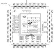
| ATXmega128A1 封装与引脚 | |
| TQFP100, CBGA100, VFBGA100 | |
ATXmega128A1 概述
ATXmega128A1, low power, high performance 8-bit AVR microcontroller featuring 128KB self-programming flash program memory, 8KB boot code section, 8KB SRAM, 2048-Byte EEPROM, external bus interface, 4-channel DMA controller, 8-channel event system, and up to 32 MIPS throughput at 32MHz. The AVR XMEGA A1 series features 100-pin packages.
The ATXmega128A1 can be used in a wide range of applications, such as building, industrial, motor, board, and climate control; hand-held battery applications; factory automation; power tools; HVAC; networking, metering, large home appliances, and optical and medical devices.
ATXmega128A1 特性
- High-performance, Low-power 8-bit AVR XMEGA Microcontroller.
- Non-volatile Program and Data Memories
- 64K - 384K Bytes of In-System Self-Programmable Flash.
- 4K - 8K Bytes Boot Section with Independent Lock Bits.
- 2 KB - 4 KB EEPROM.
- 4 KB - 32 KB Internal SRAM. - Peripheral Features
- Four-channel DMA Controller with support for external requests.
- Eight-channel Event System.
- Eight 16-bit Timer/Counters.
- Four Timer/Counters with 4 Output Compare or Input Capture channels.
- Four Timer/Counters with 2 Output Compare or Input Capture channels.
- High-Resolution Extension on all Timer/Counters.
- Advanced Waveform Extension on two Timer/Counters.
- IrDA modulation/demodulation for one USART.
- Four SPI (Serial Peripheral Interface) peripherals.
- AES and DES Crypto Engine.
- 16-bit Real Time Counter with separate Oscillator.
- Two Eight-channel, 12-bit, 2 Msps Analog to Digital Converters.
- Two Two-channel, 12-bit, 1 Msps Digital to Analog Converters.
- Four Analog Comparators with Window compare function.
- External Interrupts on all General Purpose I/O pins.
- Programmable Watchdog Timer with Separate On-chip Ultra Low Power Oscillator. - Special Microcontroller Features
- Power-on Reset and Programmable Brown-out Detection.
- Internal and External Clock Options with PLL and Prescaler.
- Programmable Multi-level Interrupt Controller.
- Sleep Modes: Idle, Power-down, Standby, Power-save, Extended Standby.
- Advanced Programming, Test and Debugging Interfaces.- JTAG (IEEE 1149.1 Compliant) Interface for test, debug and programming.
- PDI (Program and Debug Interface) for programming, test and debugging
- I/O and Packages
- 78 Programmable I/O Lines.
- 100 - lead TQFP.
- 100 - ball CBGA.
- 100 - ball VFBGA. - Operating Voltage: 1.6 – 3.6V.
- Speed performance
- 0 – 12 MHz @ 1.6 – 3.6V.
- 0 – 32 MHz @ 2.7 – 3.6V.


